- User Manual for iVMS-4200
- During live view, why the image is blurred or not fluent?
- During live view, why an error message with error code 91 prompts ?
- Why the memory leak and the client crashed after running for a while?
- If the network bandwidth is low, how to get better performance of live view and playback?
- Appendix D. Error Code
- Security
User Manual for iVMS-4200
During live view, why the image is blurred or not fluent?
Check the driver of video card. We highly recommend you update the driver of video card to the latest version.
During live view, why an error message with error code 91 prompts ?
For live view of multiple windows, the channel may not support sub stream. You should disable the function of Auto-change Stream Type in System Configuration → Image , and select the appropriate steam type for live view.
Why the memory leak and the client crashed after running for a while?
In the installation directory of the client software, open the Setup.xml file with Notepad and modify the value of EnableNetandJoystickCheck to false. Restart the client, and if the problem is still not solved, contact our technique support.
If the network bandwidth is low, how to get better performance of live view and playback?
This function should be supported by the device. You can perform the following operations to realize live view in low bandwidth:
You should disable Auto-Change Stream Type beforehand.
Firstly, after adding the encoding devices to the client, you need to set the camera's streaming protocol.
1. Enter Device Management → Group .
2. Select the camera in the Encoding Channel list and click .
3. In the Edit Camera window, set the Protocol Type (for live view) and Playback Protocol Type (for playback) as Adaptive UDP.
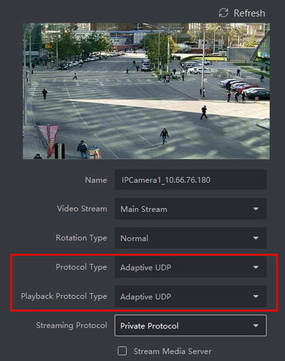
Figure C-1 Set Protocol Type
4. Click OK to save the settings.
● Select stream type for live view.
1. Enter Main View module.
2. In the device list on the left, move the cursor to the camera name and click → Stream .
Figure C-2 Select Stream Type
3. For network camera, set the stream type as Third Stream. For DVRs or NVRs, set the stream type as Virtual Stream.
4. Start live view.
Appendix D. Error Code
IVMS-4200
317 --- No videos. --- It will be prompted when the user has no permission
HCNetSDK.dll
1 --- Invalid user name or password.
2 --- No permission. --- The user in the device has no enough permission.
4 --- Invalid channel number. --- It will be prompted in the live view of remote screen.
5 --- No more devices can be connected.
7 --- Failed to connect the device.
23 --- Not supported.
29 --- Operation failed.
43 --- No buffer. --- It will be prompted when adding a device and the device port is occupied by a web server.
55 --- Invalid IP address.
56 --- Invalid MAC address.
91 --- The channel does not support the operation. --- It will be prompted when failed to get the sub stream.
96 --- The device is not registered on the DDNS.
153 --- The user is locked.
250 --- The device is not activated.
404 --- Channel No. error or the device does not support the sub stream. --- It will be prompted when failed to get the sub stream or the sub stream does not exist.
424 --- Failed to receive the data for RTSP SETUP. --- It will be prompted when adding the live view for the software DVS via external network.
800 --- No more bandwidth can be used.
Playctrl.dll
2 --- The stream is not a Video & Audio stream.
6 --- The playback window turns black when adopting H.265 in the 64-bit operating system.
Security
The Security Control Panel module provides remote control and configuration of the partitions and zones via the client software.
For the users with security control panel permissions, they can enter the Security Control Panel module to manage the security control panel and real-time alarm. For setting the user permission of Security Control Panel module, refer to Add User.
Figure 13-1 Flow Chart of Security Control Panel
● Add Security Control Device: You can add security control devices on the client. For more details, refer to Add Device .
● Group Zones/Radars: You can group the added zones/radars into groups for convenient management. For more details, refer to Group Management .
● Configure Zone Event: By configuring linked actions of zone event on the client, you will be notified once the event is triggered. For more details, refer to Configure Client Linkage for Zone Event .
● Remotely Control Security Panel: You can remotely security control panel, including partition, zone, relay, and siren. For more details, refer to Remotely Control Security Control Panel .
● Add Zone/Radar on Map: You can add zone/radar to the map as hotspots. For more details, refer to Add Zone as Hot Spot and Add Security Radar as Hot Spot .
● Map Application: You can locate the resources, view alarm information and perform related control. Refer to Map Management .
Configure Security Control Panel Remotely
After adding security control panel to the client, you can go to the remote configuration page to configure related parameters of the device via the client. For the device added by Hik-Connect, if the second verification is enabled, you need to enter the user name and password of the device for remote configuration. It is widely used for the batch device maintenance scenario. For example, the installer can log in via Hik-Connect account and remotely maintain the devices of the end user.
Steps
1. Select Device Management → Device → Device .
2. Select the added security control panel, and click on Operation column.
3. Optional: For the device with the second verification enabled, enter the user name and password of the device, and click OK. Result The remote configuration page will be displayed.
Configure Client Linkage for Zone Event
Even if you are far away from a zone, you can still know what happens and how urgent the event is in a zone by configuring linked actions of zone event on the client. You will be notified on the client once an event is triggered, so that you can response to the event instantly. You can also configure client actions of multiple zones in a batch at a time. Before You Start
● Make sure you have added a security control panel.
● Make sure zones have been defined beforehand.
● Make sure events have been configured beforehand.
Steps
1. Click Event Configuration → Alarm Event .
2. Expand the zone list of a security control panel, and then select a zone from the list.
3. Check one or more event.
4. Click Edit Linkage to configure client actions. Audible Warning The client software gives an audible warning when an event is triggered. You can select the alarm sound for audible warning.
Send Email
Send an email of the alarm information to one or more receivers. For details about setting email parameters, refer to Set Email Parameters .
Pop-up Window
Pop-up window to display the event related information (including event details, captured pictures of the linked camera, process record, and process field) on the software client when the event is triggered.
Display on Map
When the event source is added as a hot spot on the map, the hot spot will be displayed with red number (indicates the number of events, and the maximum number is 10) aside when the event is triggered, which helps the security guard to view the location of the event. You can also click the hot spot to view the event details and the live video of the linked camera (s).
Linked Camera
Link the selected camera(s) to capture picture when the zone event is triggered. Select the camera(s) in the drop-down list.